A Manual Programmer for 82s129, 82s126, 74s287, and 74s387 PROM Chips
Program vintage PROM chips without an expensive programmer
Introduction
The 82s129, 82s126, 74s287, and 74s387 are PROM chips that were commonly used in older arcade games, vintage PCs, and equipment from the 1970s and 80s. Many modern programmers don’t support these chips, often making vintage electronics projects difficult to complete. This manual programmer can be used to read and write these chips.
PROM chips are written by blowing tiny fuses inside the chip and can only be written once — if you mistakenly pulse the wrong bit on, you’ll need to start over with a new chip. When completing this board, it’s advisable to practice pulsing some blank locations on an already-written “scratch” chip, as I do in the video below.
Note: We also have an 82s123 version.
Video
Parts List
Pictures
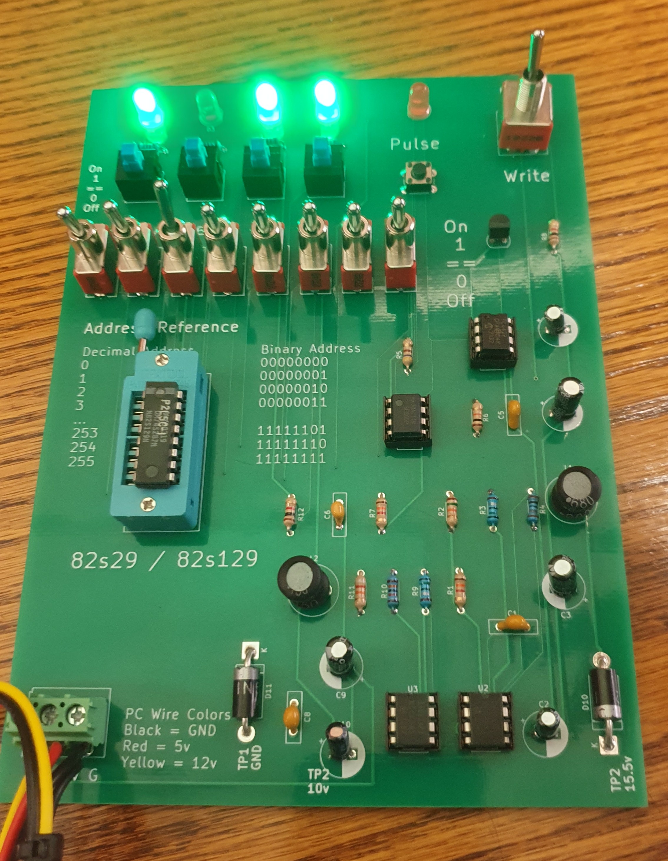
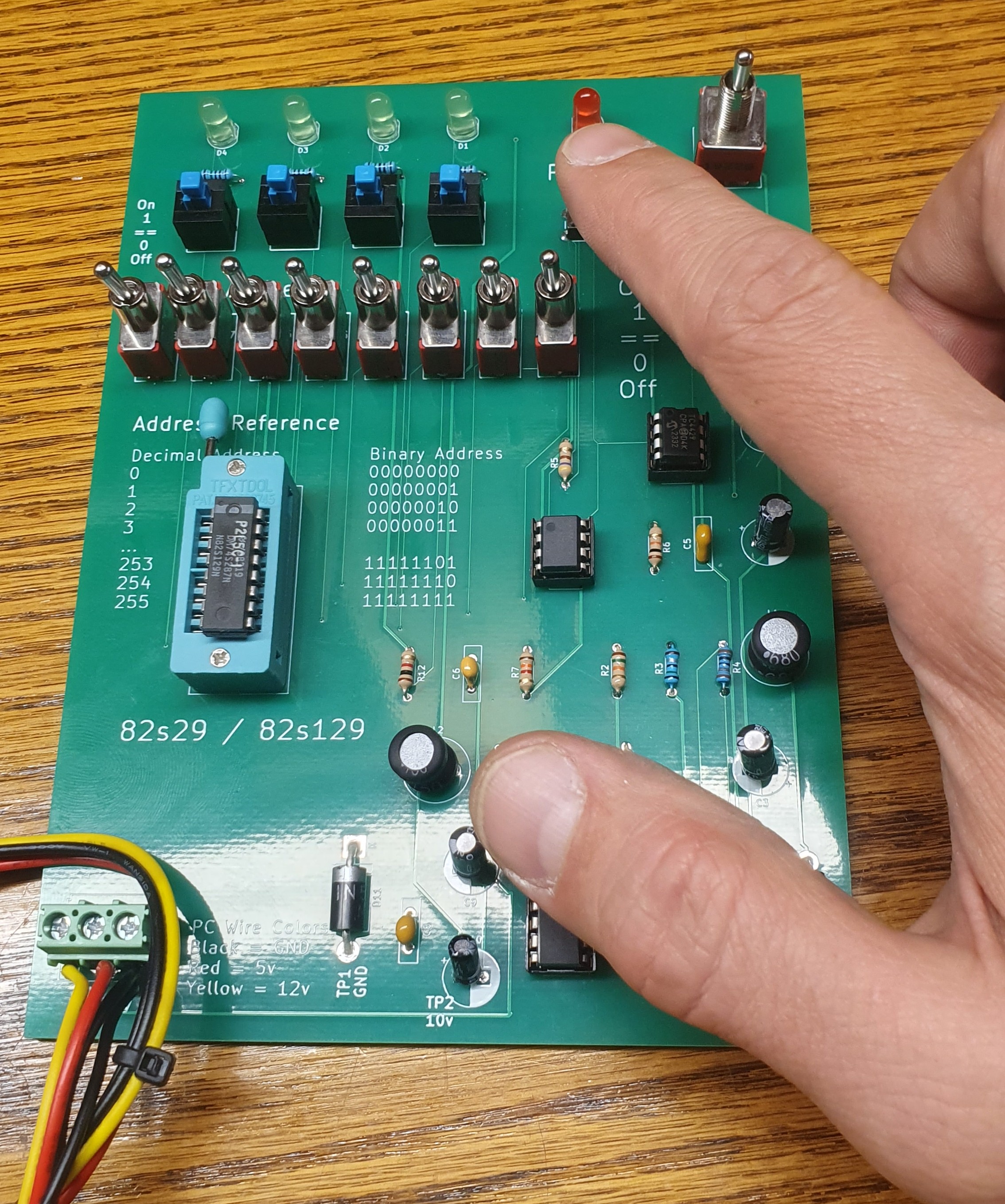
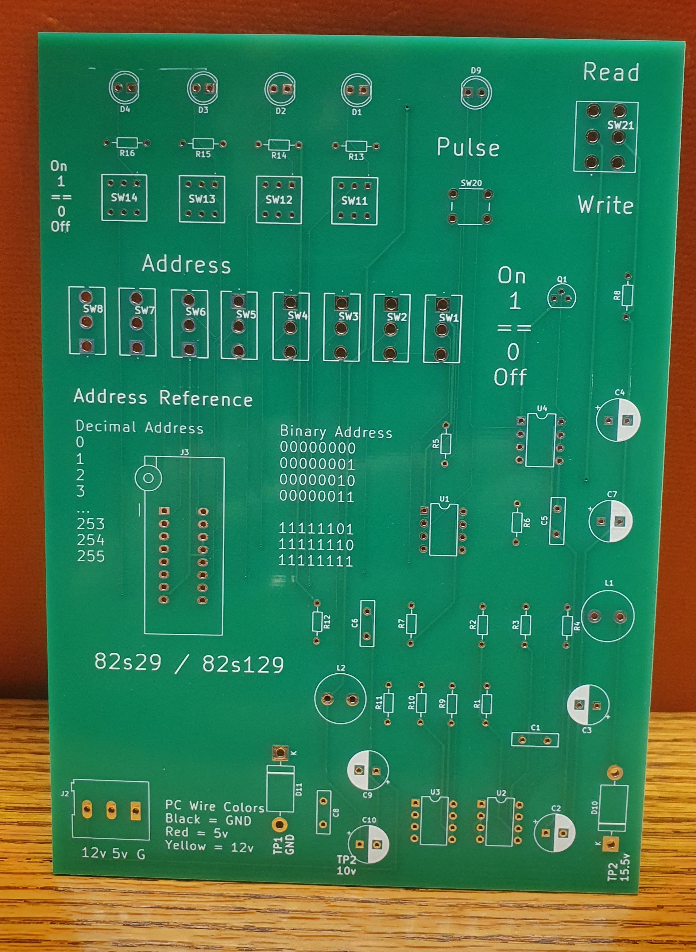
Operation
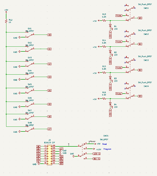
How do I use it? This programmer is manual and requires understanding of both binary and hexadecimal numbers. These chips are made up of 256 addresses, each of which holds 4 bits of data. Both the addresses and the bits are just 1s and 0s, but the data you need to write will often be in hex format.
Example: Let’s say you want to write the value “E” to address “100.” To do this, we need to figure out the binary values for both E (hex) and 100 (decimal). There are many hex-to-binary converters available online if you’re unsure how to do this.
E converts to 1110. This is the value we want to write to the chip, shown on the LEDs as: On‑On‑On‑Off.
We need to write this to address 100. Since 100 is decimal, let’s convert that to binary too.
100 converts to 1100100 in binary, but that’s only 7 digits wide, so we add a leading 0: 01100100.
01100100 is the address we want to write to. To get to this address, set the switches to match this pattern:
01100100 = Down‑Up‑Up‑Down‑Down‑Up‑Down‑Down
Once at the correct address, pulse On‑On‑On‑Off to the LEDs.
Repeat for all 256 addresses.
Power
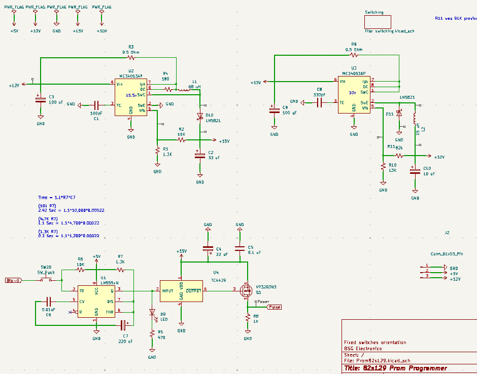
This board requires +5V, +12V, and ground, which can be tapped from a PC or arcade power supply. For a PC power supply, you can use a standard hard drive power connector.
Assembly
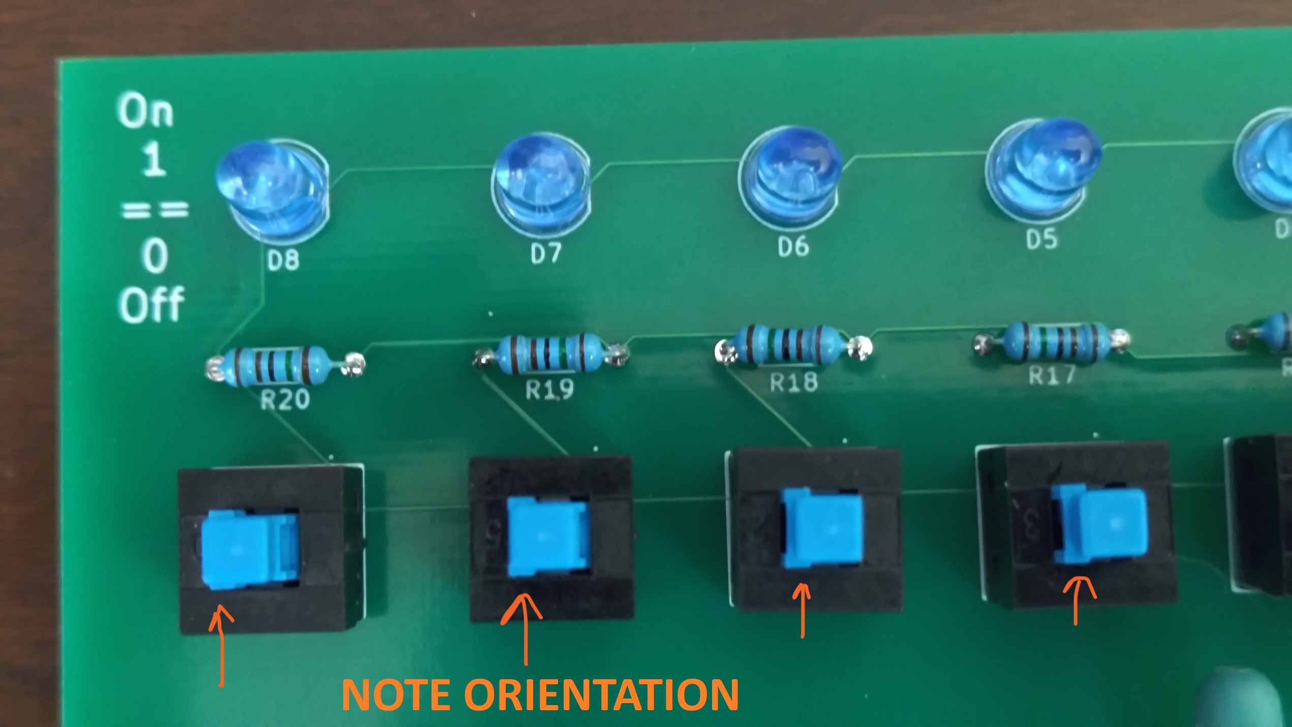
Note the orientation of the blue push buttons — don’t accidentally install these backwards!
Buy It
Available at:
Digikey List (Key Parts)
Schematics
Version History
All boards being sold today are version 1.1, which is not known to have any errors. You’ll receive a version 1.1 board even if some of the video and pictures still show the 1.0 version number. If you have a v1.0 board and are experiencing issues, please contact me for a fix or replacement.