4116 Memory Tester Video And Assembly Instructions
How it works
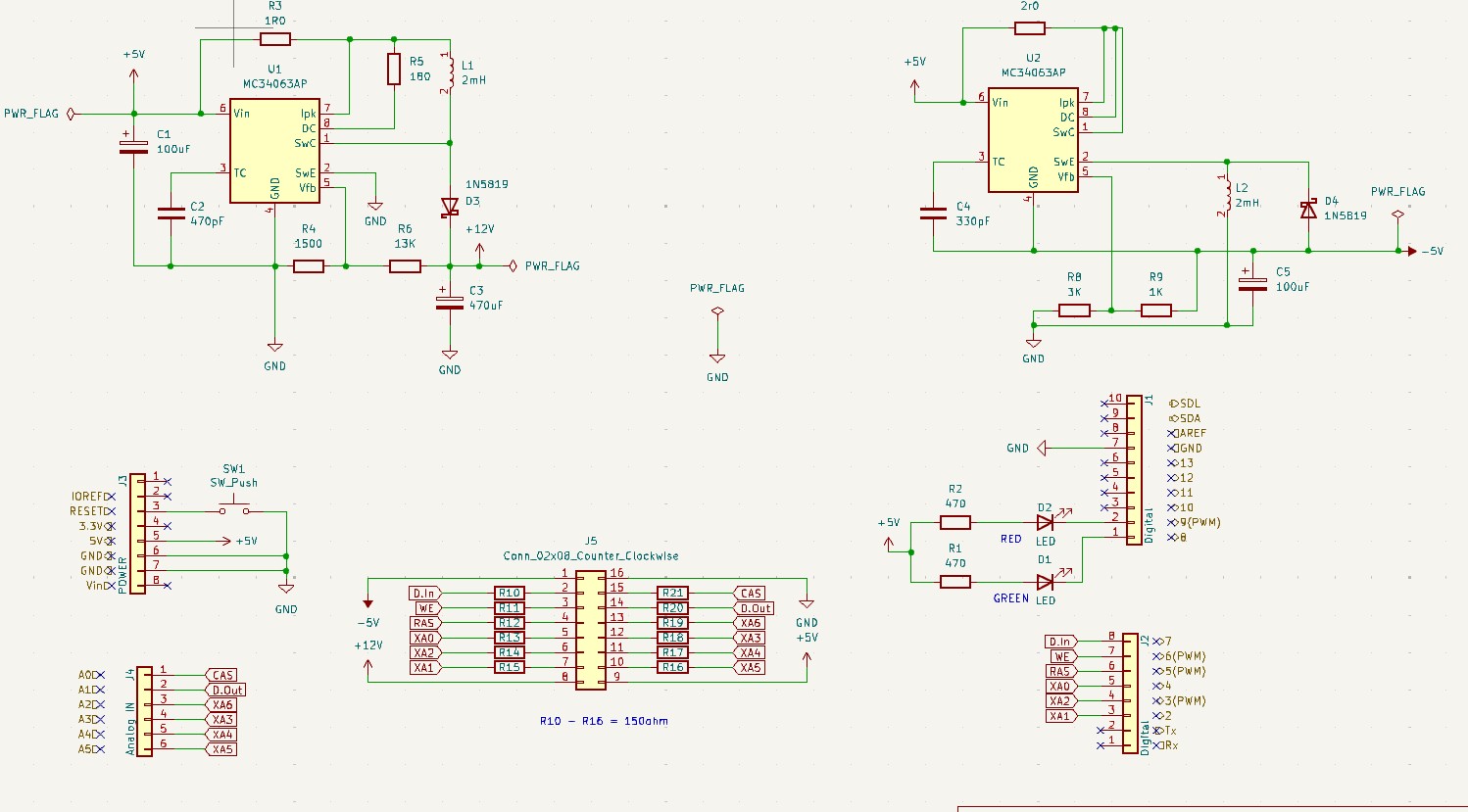
Schematic and BOM Download
Assembly Instructions
You will also need a soldering iron, an Arduino Uno, wire cutters, and a PC with a USB port.
-
Identify the included parts. These are the parts included in the kit.
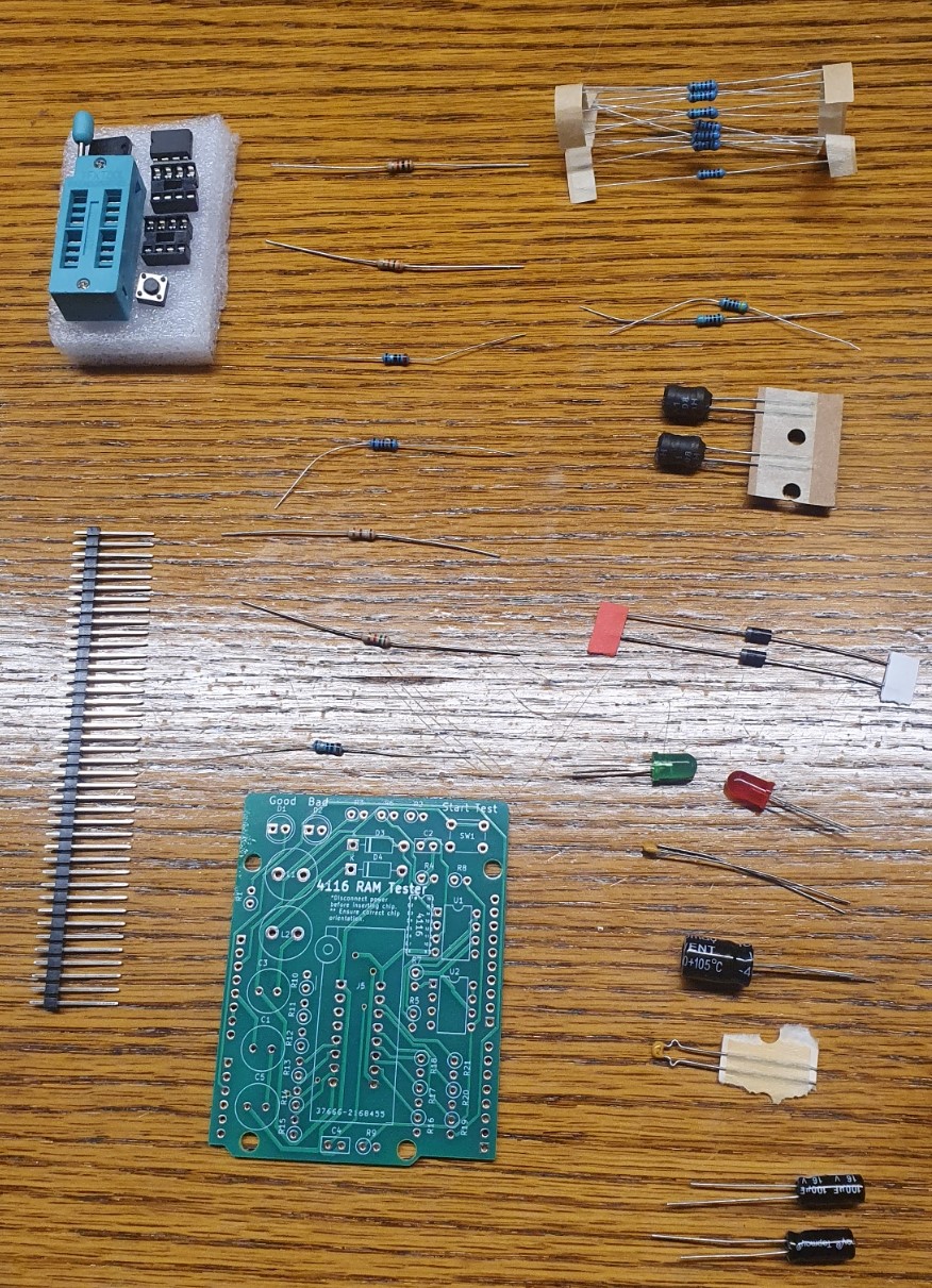
-
Assemble the upper components. Insert components based on the item IDs on the inventory sheet. Make sure LEDs, capacitors, and diodes are inserted with the correct orientation, matching the pictures below.
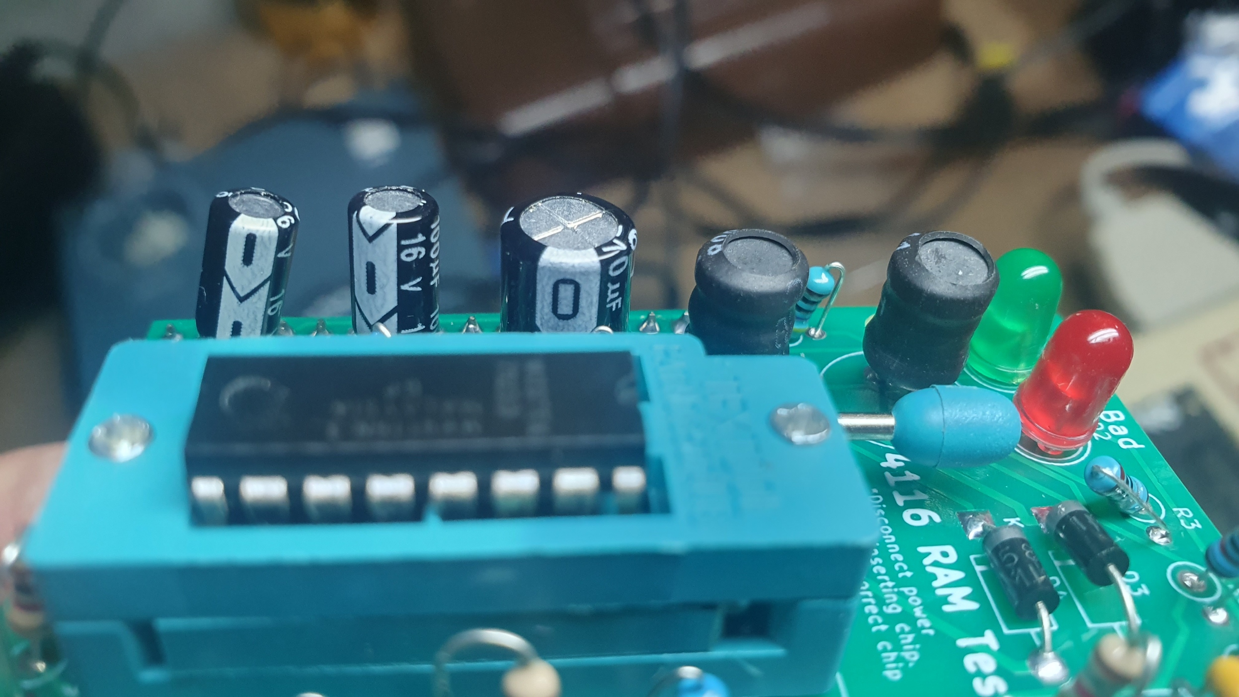
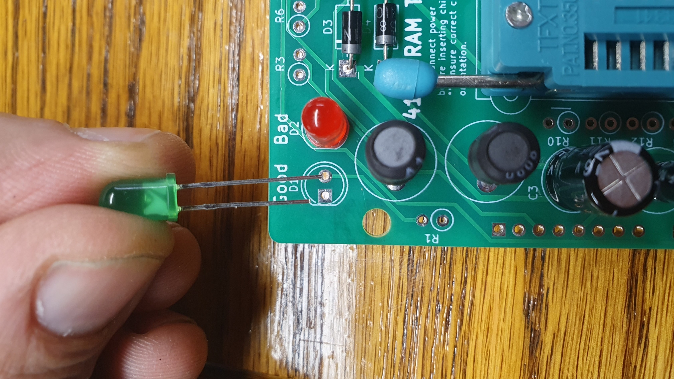
-
Flip the board over and solder in the components. Ensure that extra solder does not connect any pins. Trim the extra wire length off the LED legs.
-
Clip and insert the riser pins. Clip to size and insert the riser pins from the bottom, then solder in from the top.
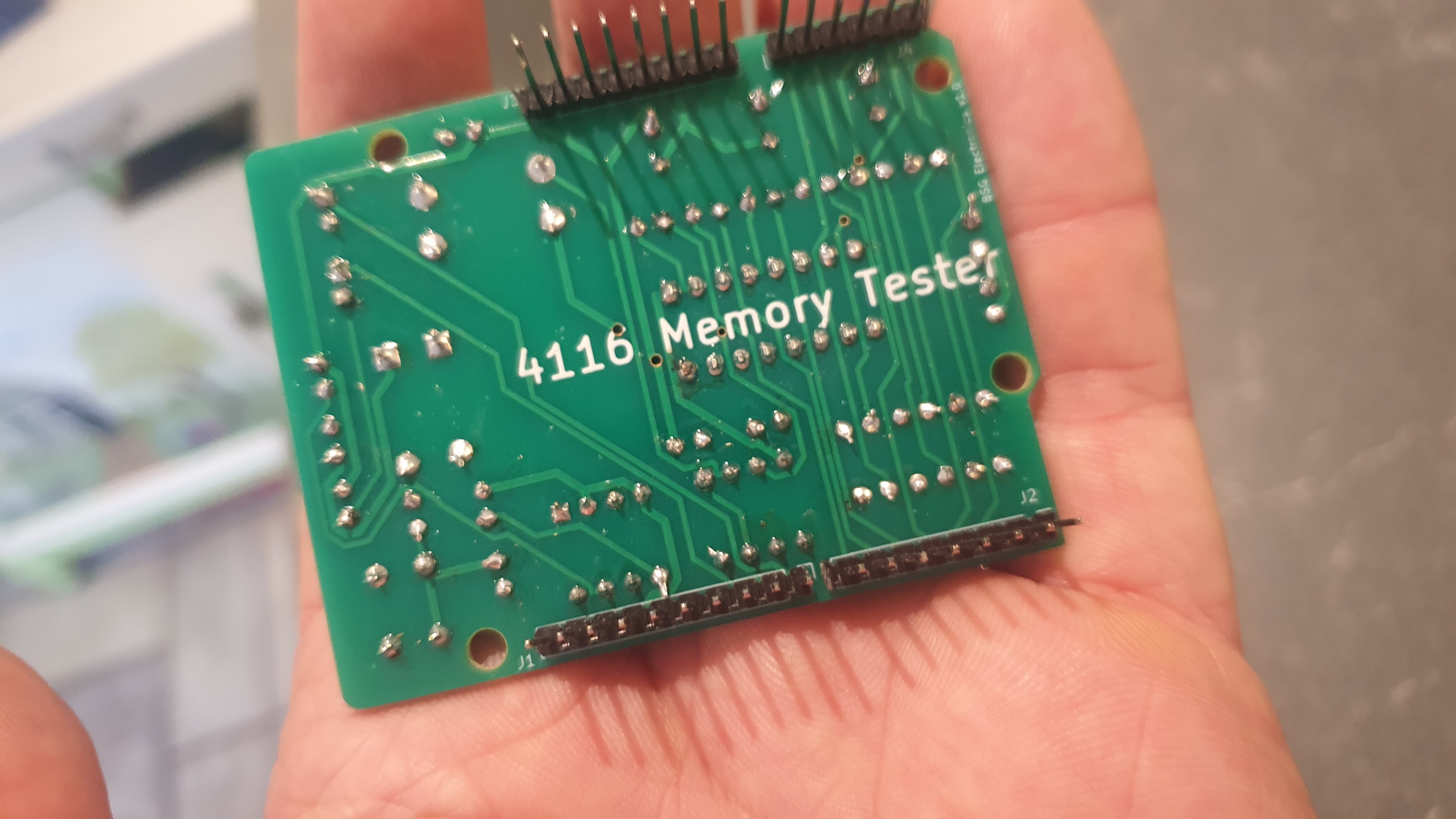
-
Install the completed shield on your Arduino Uno.
-
Install the Arduino IDE. Download and install the Arduino IDE software.
-
Download the 4116 memory test source code. Go to the 4116MemTest repository, select Code > Download ZIP, then extract the ZIP file and save
4116.ino. -
Connect your Arduino Uno to your computer via USB.
-
Configure the Arduino IDE. Launch the IDE and make sure Arduino Uno and your correct COM port are both selected under the Tools menu.
-
Open the sketch. Select File > Open, then select the
4116.inofile you downloaded in step 7. -
Upload the sketch. Select Sketch > Upload to load the code onto your Arduino.
Using the 4116 Tester
-
Insert the 4116 chip to be tested into the ZIF socket.
Important: Ensure the chip is inserted with the notch facing up, toward the LEDs. Inserting it backwards can damage the chip.
-
Plug the Arduino in with a 9V power supply or USB. Testing begins automatically when power is connected.
-
Testing runs for about 10 seconds and displays: solid green = good, solid red = bad.
-
It’s possible to insert chips with the tester already plugged in, but make sure pins aren’t crossed and the chip has the correct orientation.
-
Press the button to run additional tests.
Troubleshooting
Verify you have the correct voltages at the locations shown below. Incorrect or missing voltages can be caused by improper assembly — check for solder bridges, resistors in the wrong locations, or chips installed backwards.
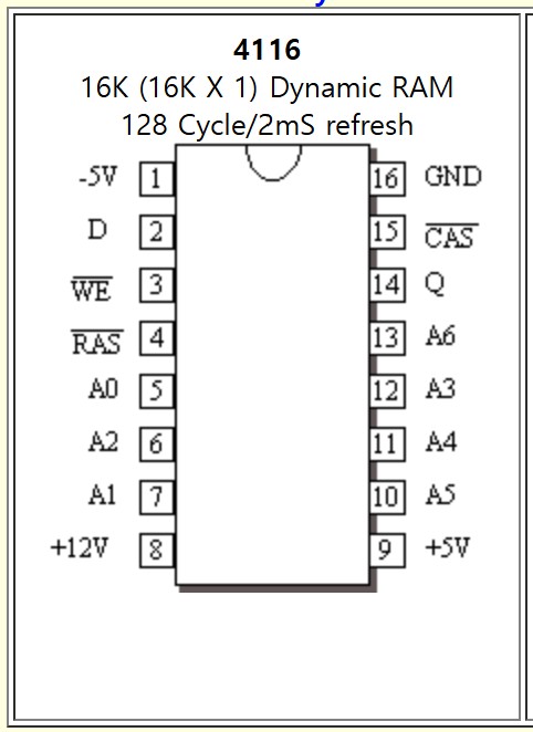
Schematic