Chicken Coop Motor Drive
Motor reversing door controller board for use in chicken coops
Introduction
I’ve had chickens for the past 10 years and have gone through multiple iterations of controllers to open and close a door via a linear actuator. The circuit required is pretty simple, but wiring quickly becomes messy as extra features and functions are added. This board was created to simplify all the messy wiring and functions of my custom coop controller.
Videos
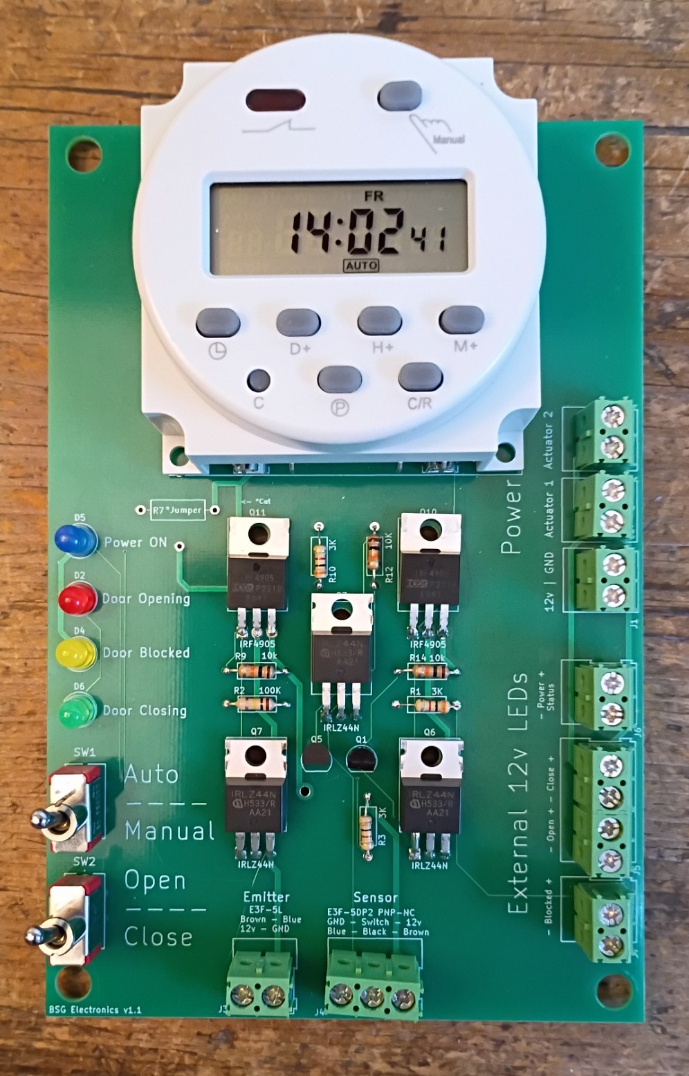
Key Features
-
Detachable timer — bring the timer inside and program it indoors in a warm house, in good light, with your glasses.
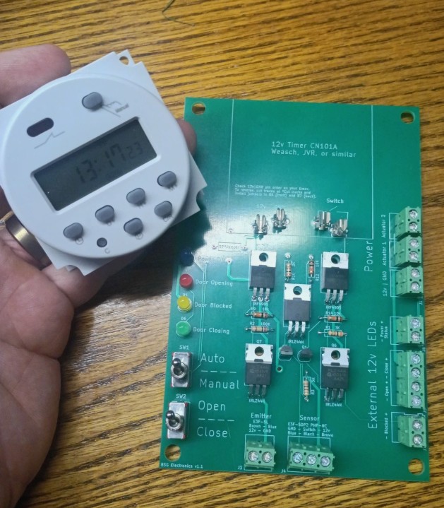
-
Manual override — open or close the door without changing the timer.

-
External status LED hookups — instantly see door status at night via colored LEDs.
-
Multiple linear actuator outputs — with photoelectric safety cutoff that stops motion if a chicken is blocking the door.
Assembly
Assembly requires soldering. All solder-side parts are included.
Buy the Kit
Available as a solder kit from either:
Parts Not Included
I’m selling this board as a solder kit. To keep the cost low, the following items you’ll need to buy yourself:
- Weasch CN101A 12V Timer — available on Amazon. Other timers might work, but get this one to ensure the connectors line up exactly.
- External 12V LEDs — used to display door, power, and beam status. Available from eBay: option 1, option 2.
- Photoelectric emitter and sensor — I suggest one “E3F-5L” emitter and one “E3F-5DP2” sensor (PNP, normally closed). Available on eBay.
- Power supply — this board is designed to run on 12V DC. Be sure to use a supply that can deliver enough amperage to power your linear actuator(s); I’m using this 5A supply from Amazon.
- Linear actuator — the PCB can control one or two actuators. I used these from eBay.
Build Instructions
Insert and solder components into the PCB, matching the labels on the PCB’s front silkscreen. A few things to be aware of:
-
Glass fuse clips are used to hold the timer’s spade blades in place. Before soldering them in, break off and discard the small end tab, then gradually bend the fuse holder sides in using needle-nose pliers. Ensure both sides touch each other and are centered. A few extra clips are included in case you break one.

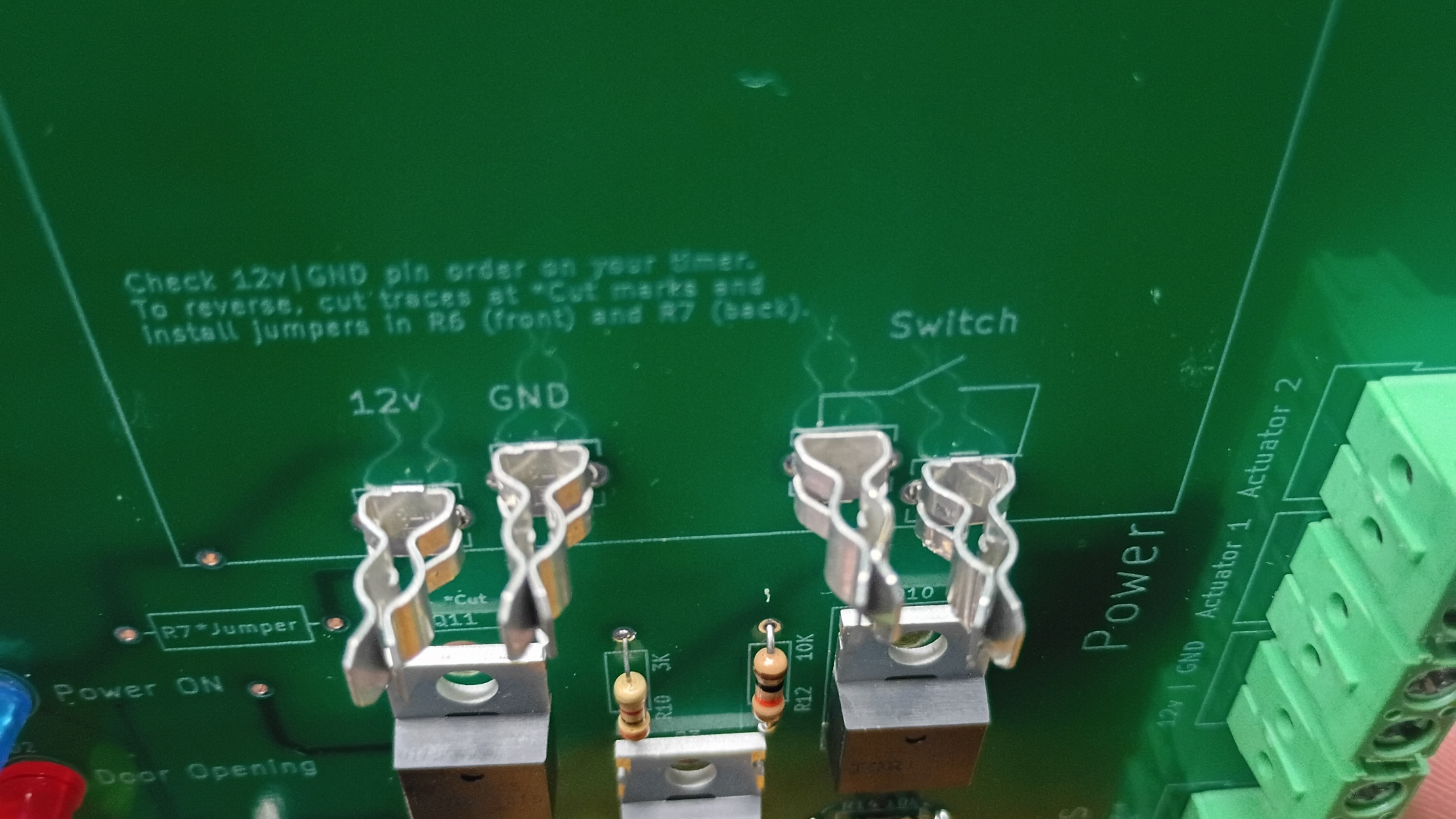
-
Center transistors: the two small transistors in the center of the board aren’t labeled on the silkscreen. Ensure the VP3203N is on the left and the 2N7000 is on the right.
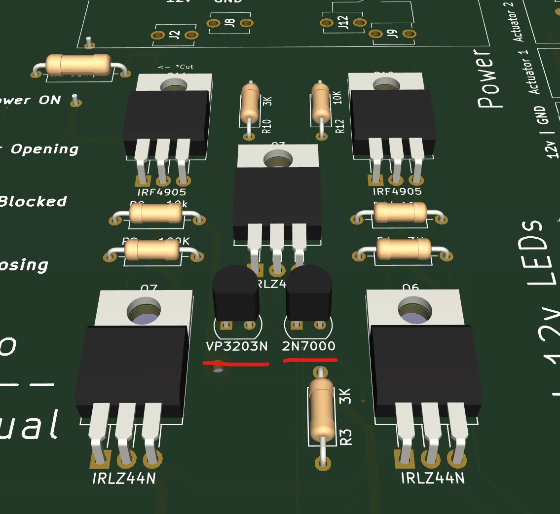
-
LED polarity: make sure you get this right. The long leg of the LED is positive and should be positioned away from the flat side of the silkscreen symbol.
Polarity Swap (should not be needed!)
The timer polarity can be swapped by cutting two traces and adding two jumpers. Some older models of this timer had the polarity reversed, but I don’t believe that version is even sold anymore.