Boston MBTA Live Subway Tracker with ESP32
Boston MBTA Live Subway Tracker with ESP32
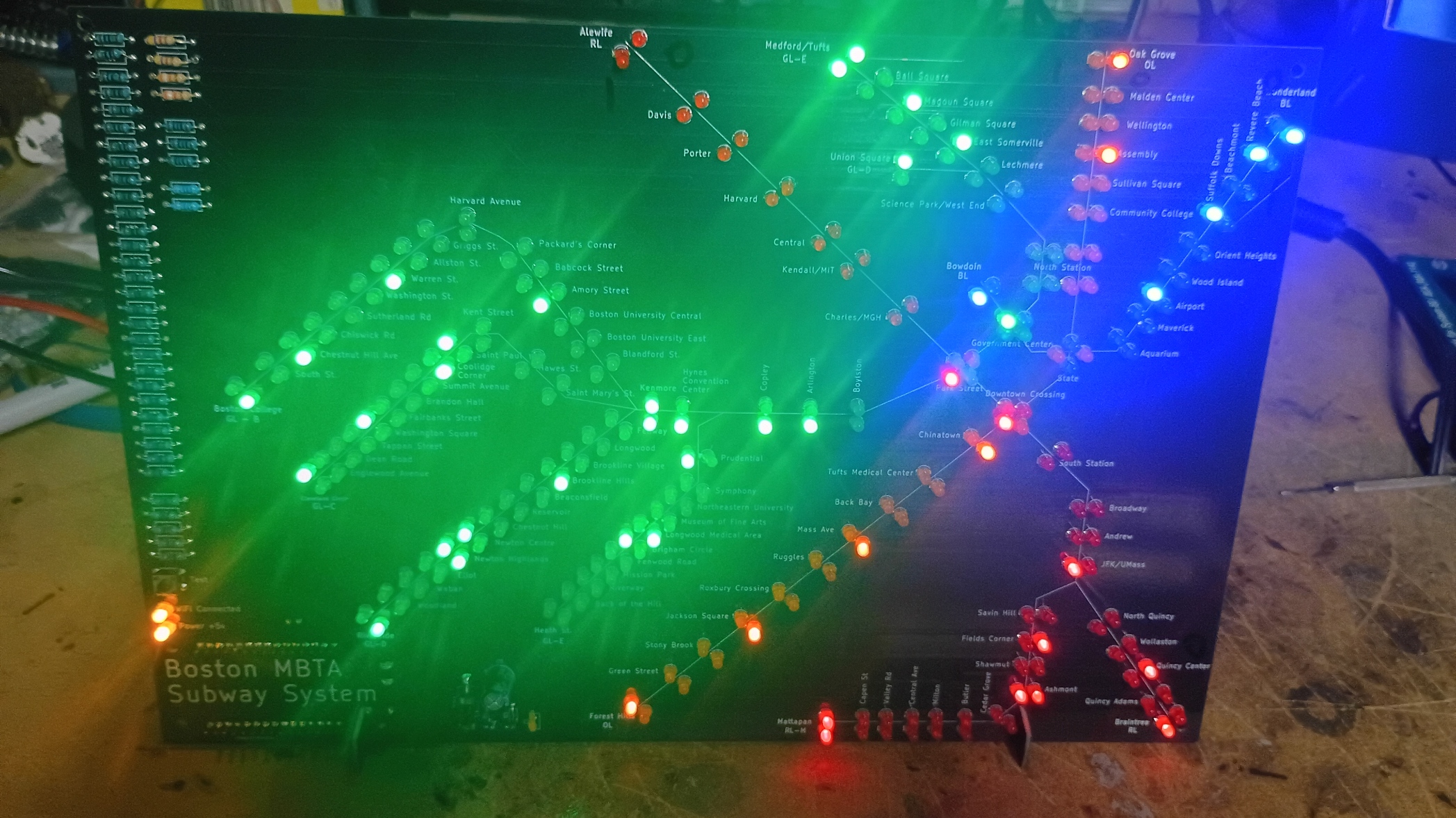
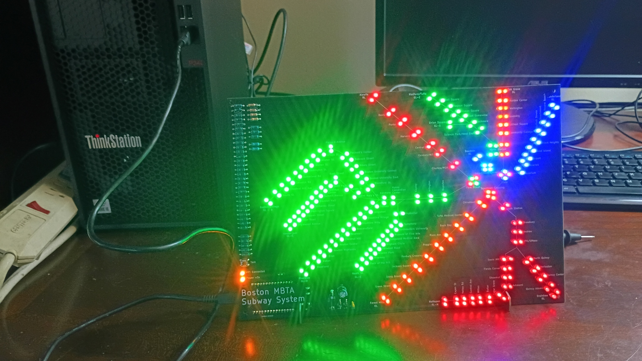
This DIY solder project turns the Boston subway map into a live display. An ESP32 connects to Wi-Fi, downloads current vehicle data from the MBTA V3 API, and lights the LEDs for the stations where trains are stopped or currently headed.
Project Overview
The tracker covers the MBTA Red, Orange, Blue, Green, and Mattapan lines. Each station has separate LEDs for the two directions of travel, making it possible to see activity across the system.
Three HT16K33 LED-driver chips control the large number of LEDs over a shared I2C connection. These 3 chips are surface mount and come pre mounted on the PCB. The ESP32 polls the MBTA vehicle feed approximately every 15 seconds, matches each train’s route, stop, and direction to the corresponding LED, and then updates the map.
The display uses two LED states:
- Solid LED — a train is stopped at that station.
- Blinking LED — a train is incoming or traveling toward that station.
A status LED shows whether the ESP32 is connected to Wi-Fi. The test button can display each direction separately or light the complete map, which is useful while assembling and troubleshooting the board. Holding the button again can put it in a solid-only modes if you prefer to not see blinking.
Can I build this?
This kit requires soldering of 280+ LEDs, 100+ resistors, and many other components. If you’ve build solder kits before and are ready for a mega-size kit, this one is for you!. If you have never soldered before, you’ll probably want to start with a simpler kit first.
This kit uses 3x HT16K33 led driver chips. This type of chip is only available in surface mount and has been pre-soldered on to the boad.
Main Hardware
- Custom MBTA map PCB and PCB legs.
- ESP32 development board
- Three SMD HT16K33 LED-driver ICs pre soldered on the board.
- Station LEDs
- Wi-Fi and power status LEDs
- Test push button
- Resistors, capacitors, and other supporting components
What You Will Need
- A soldering iron with a fine tip
- Electronics solder
- Flush cutters
- Needle-nose pliers
- Computer with a USB port
- Arduino IDE
- Wi-Fi network credentials
- MBTA V3 API key
- 5v DC power adapter.
Prep Steps
- Get your own MBTA key. You’ll need this to customize the esp32 sketch before uploading it.
https://www.mbta.com/developers/v3-api
- Download the firmware sketch and edit it with your Wifi SSID, WiFi Password, and your MBTA key
- Connect the esp32 to your PC via a USB. Install the Arduino IDE and ensure you can connect to the ESP32 https://support.arduino.cc/hc/en-us/articles/360019833020-Download-and-install-Arduino-IDE
- Upload the sketch to your esp32. Ensure it lights up and that it is functioning before you begin soldering it in place.
- You may need to install esp32 drivers before you can connect the esp32 to your windows pc. I n
https://support.arduino.cc/hc/en-us/articles/360019833020-Download-and-install-Arduino-IDE https://www.silabs.com/software-and-tools/usb-to-uart-bridge-vcp-drivers?tab=downloads
Starter Assembly Instructions
Assembly Tips: Review the layout of the parts to ensure you know where everything goes. NOTE - .
-
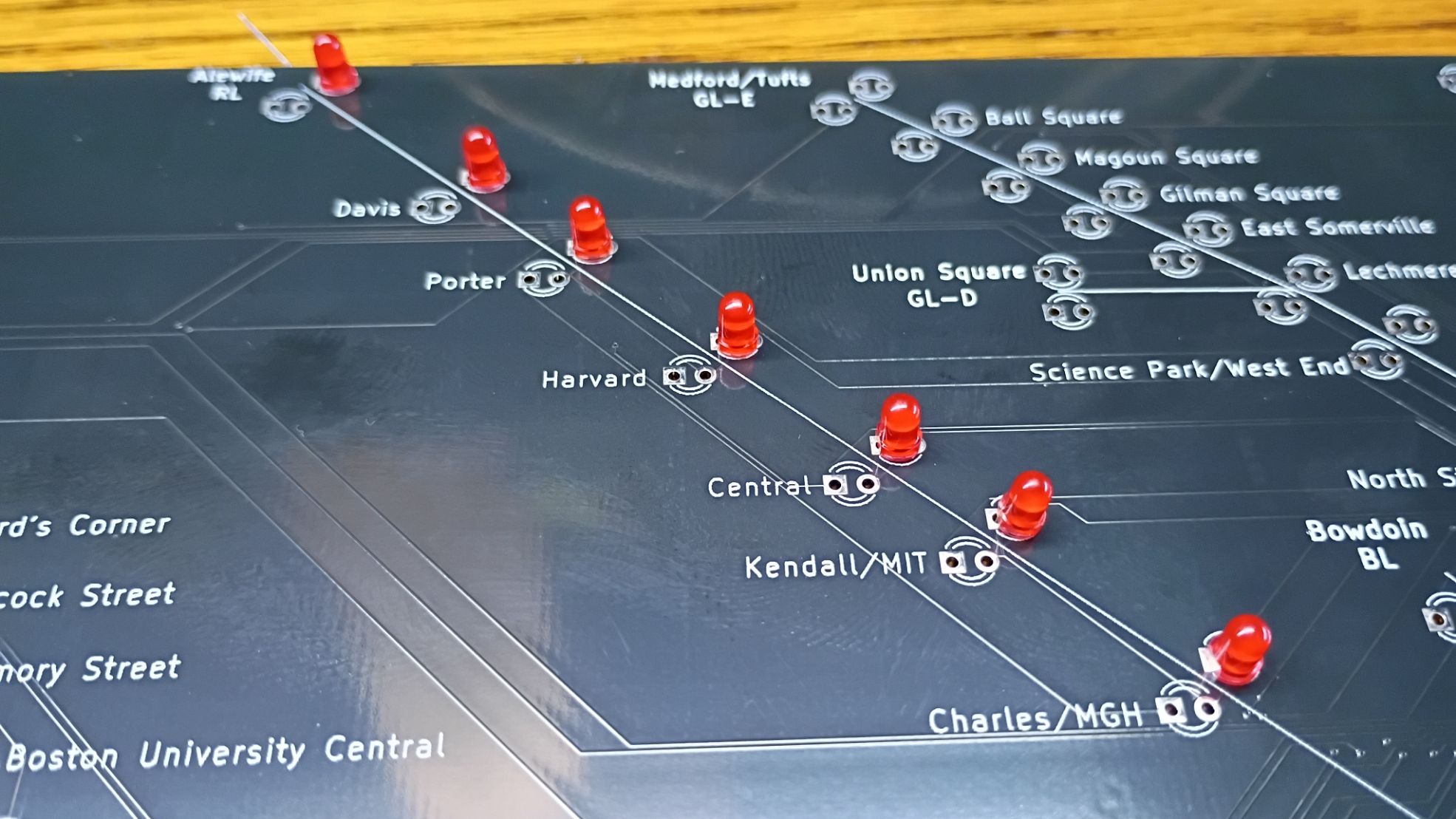
Diode and LED orientation LEDs and Diodes MUST be installed in the correct orientation. Backwards installed LEDs will not work! Diodes should have the stripe matching the stripe on the silkscreen background. LEDs should have the long leg installed into the circular hole and the short leg installed into the square hole.
-
Assembly Order The inbound and outbound stations are very close together making it easy to possibly get a solder bridge between wires. I had better luck installing, soldering, and trimming one side of the line first.
-
SLOW DOWN when trimming wires! There are hundreds of small traces across the pcb connecting to each LED location. Resist the temptation to move quickly when clipping wires as it is very easy to nick a trace with your cutters. Go slow and make sure you don’t scratch the PCB surface.
-
Only connect 1 power supply and ensure correct polarity. The kit can be run via USB to the esp32, but the power draw is close to the limit of what the esp32 board can deliver. For this reason, it is not recommended to run the board full time via USB. The board can be run via a 5v AC/DC wall adapter either via barrel jack or wires into screw terminals. Only connect one option at a time! You are responsible to make sure you have positive connected to positive and negative to negative! If you need an adapter, I recommend this one from Amazon.
-
Run the LED test. Briefly press the test button to cycle through direction 0, direction 1, and all LEDs. Check for LEDs that do not light or appear in the wrong direction. If you do have a dead led, it may be in backwards. Look closely inside the plastic and compare the internal orientation with other working leds.
Using the Tracker
- A short press of the test button cycles through the two travel directions and then all LEDs.
- A long press returns to the live display and toggles moving trains between blinking and solid display modes.
- The map refreshes automatically from the MBTA feed.
- If Wi-Fi or the API is temporarily unavailable, the tracker retries automatically rather than requiring a reset.
How the Software Works
The ESP32 requests live subway and light-rail vehicle records from the MBTA V3 API. Each response identifies a route, a stop, a direction, and the vehicle’s current status. The firmware uses a station lookup table to translate that information into an HT16K33 address, row, and column for one physical LED.
The three LED drivers use I2C addresses 0x71, 0x72, and 0x75. They share the same data and clock lines, allowing the ESP32 to control the complete map with only two I2C pins. The firmware also includes alternate MBTA stop IDs used by some platforms and branches so that trains continue to appear at the correct station.
Troubleshooting
Several LEDs do not light
Look for a common unsoldered pin, solder bridge, or damaged trace. If an entire group is dark, verify the associated HT16K33 orientation, address configuration, power, ground, SDA, and SCL connections.
The Wi-Fi status LED stays off
Confirm the network name and password in the sketch. The ESP32 must be able to reach a 2.4 GHz Wi-Fi network with internet access.
Buy the Kit
This project is currently in development. Kit ordering information will be added here when it is available.