Binary Clock Kit - Build Instructions
Tell time in Binary
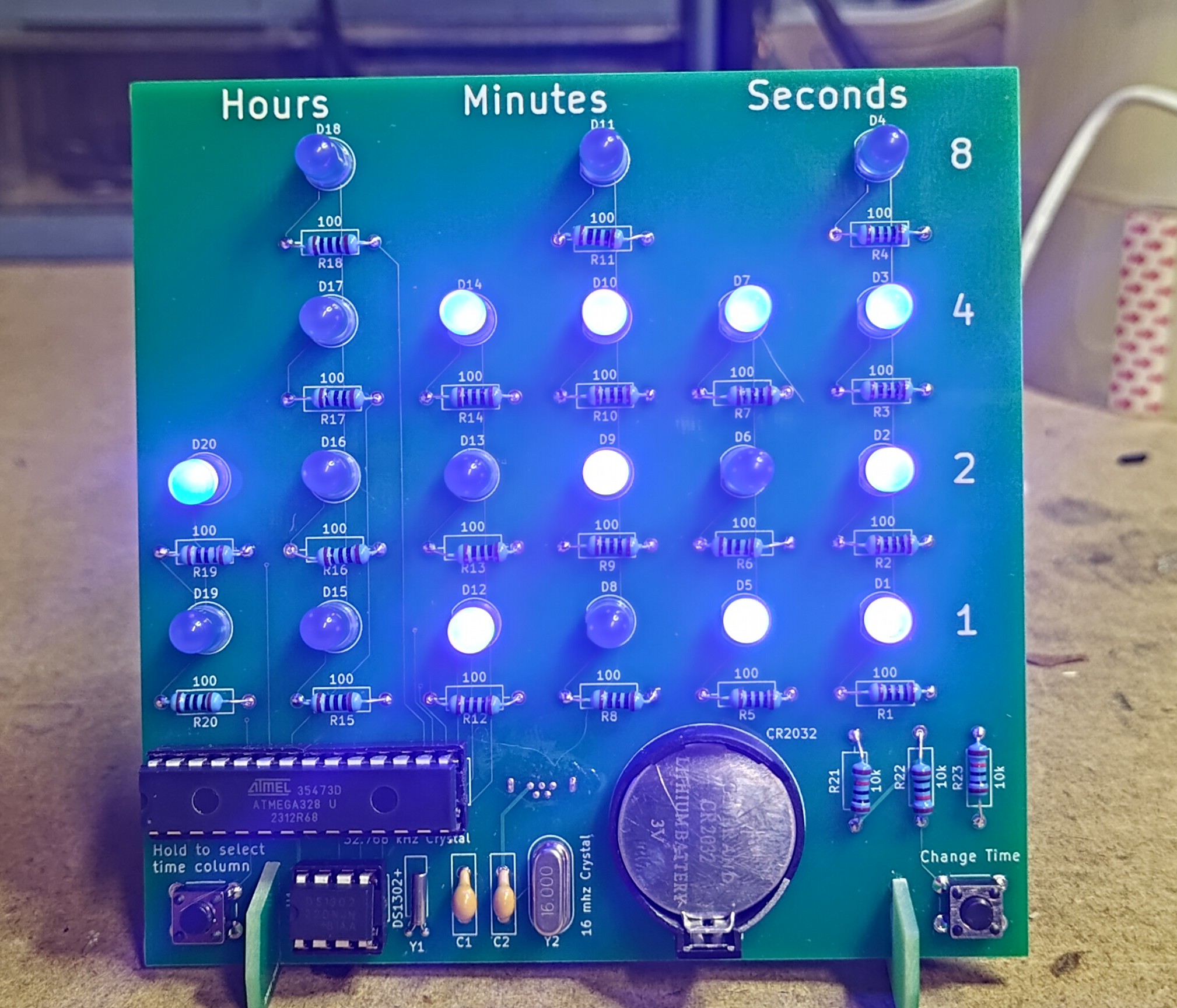
Overview and Setup Instructions
Assembly Details
Most of the components installed in this clock can be installed in either orientation. There are a few components to watch out for:
-
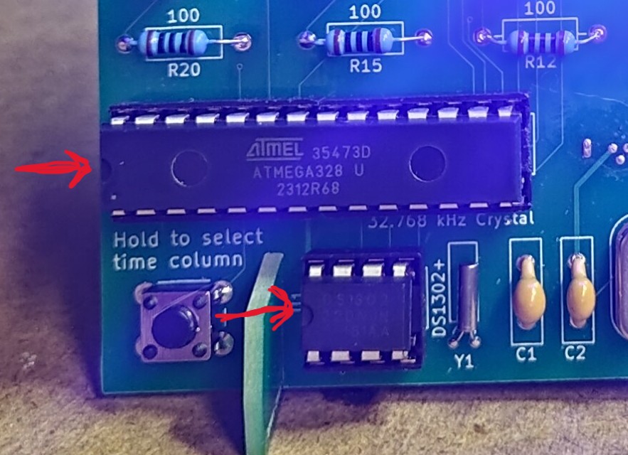
ICs — Ensure both ICs are installed with the dimple facing the left side of the clock, as seen below.
-
USB Socket — The USB socket should be installed on the back side of the board.
Important: Be careful not to get the USB socket too hot, or you may melt and short out the inside of the socket. Also ensure there are no solder bridges between any of the pins.
-
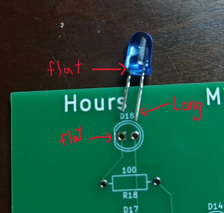
LEDs — Ensure LEDs are installed with the negative side connected to the flat side of the silkscreen on the board. The positive side of the LED (the longer leg) should be inserted in the hole opposite the flat side.
-
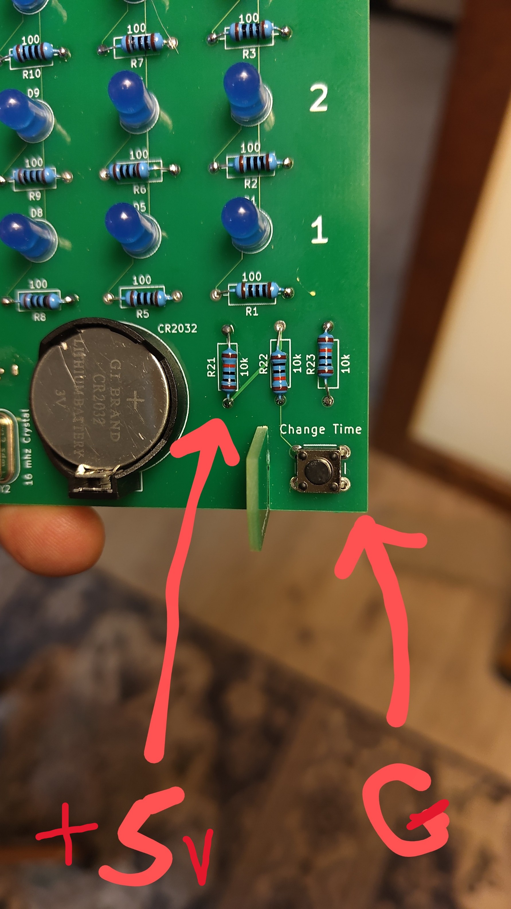
+5V and GND Test Points — Voltages can be tested from the bottom of R21 and the time change button.
-
Legs may require a drop of glue if they feel loose.
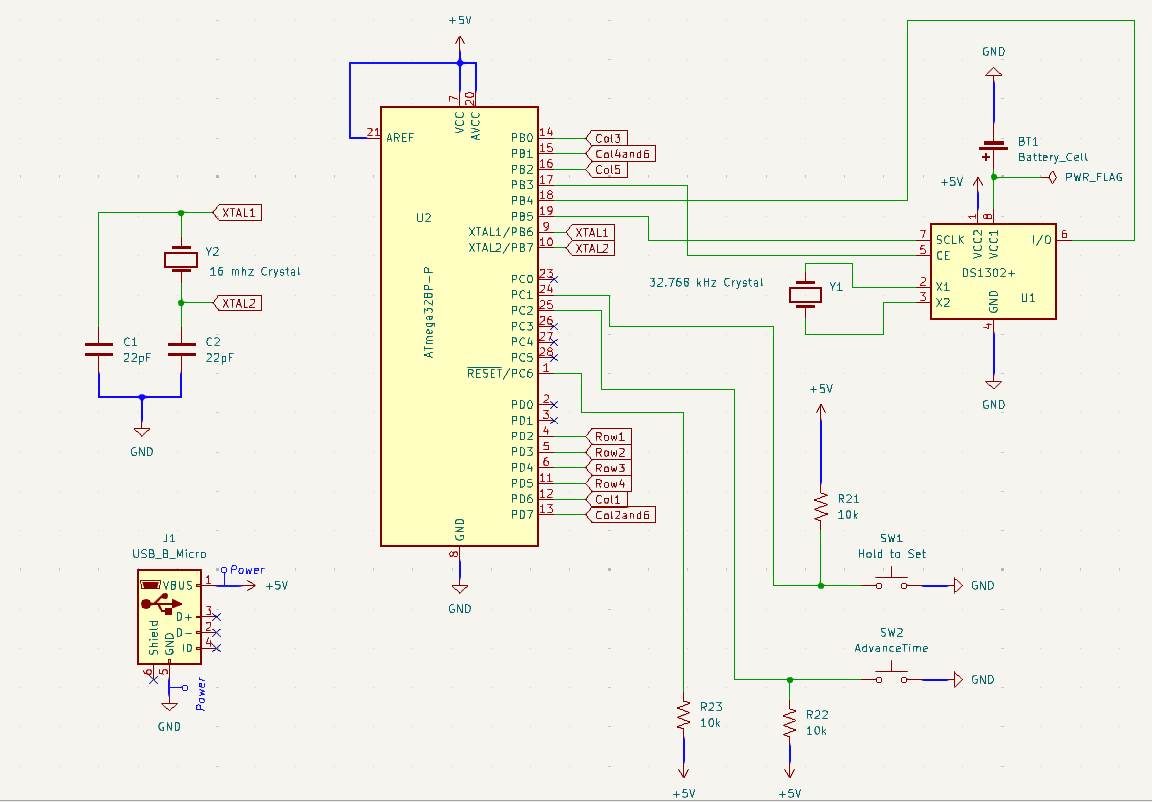
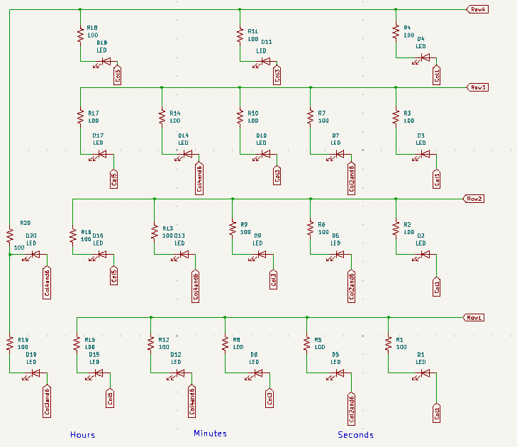
Circuit Schematics
Operation
Try to avoid touching the solder points on the back side of the clock board while it’s plugged in and running. Touching the solder pins on the back may sometimes cause the clock display to turn off — the clock will still be keeping time, just the LEDs will be off. If this happens, disconnect the power plug and plug it back in to restart the LEDs.
Buy Kit Here
Troubleshooting
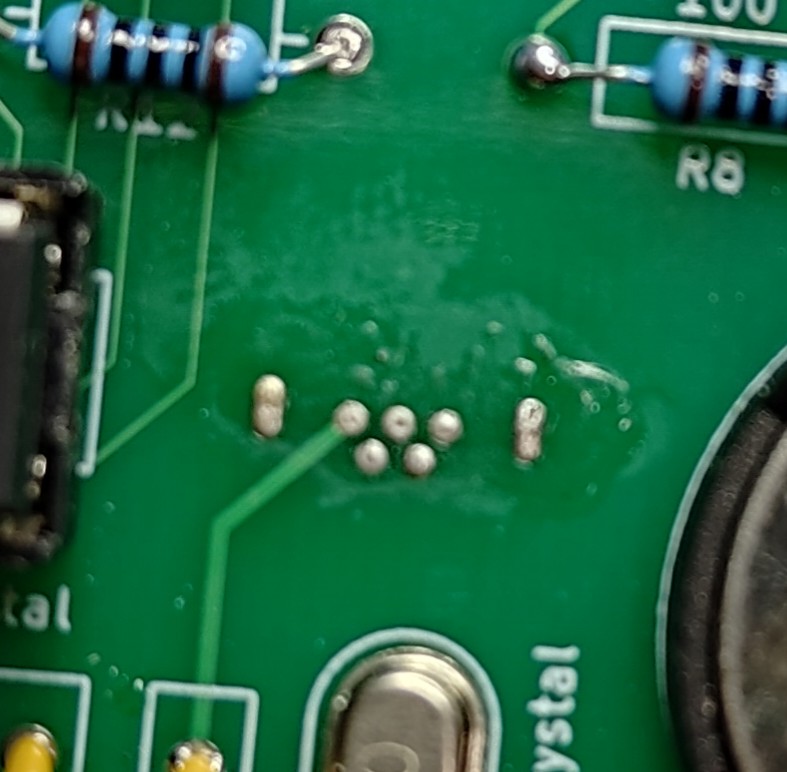
If you notice a problem where the clock appears to run too fast or skips numbers, this may be caused by the 32.768 kHz crystal starting incorrectly. Usually this can be fixed by disconnecting the power and battery and allowing the clock to sit for a few minutes.
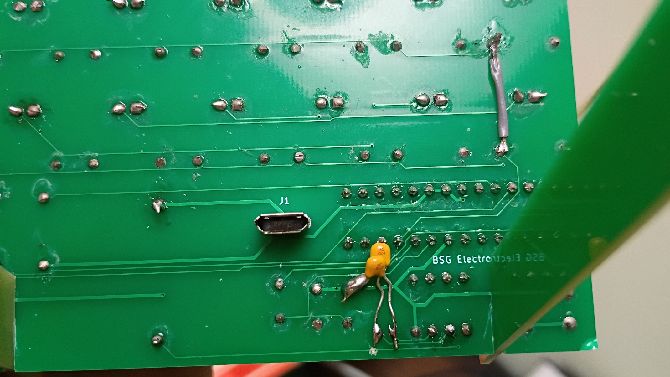
Typically you shouldn’t need to do anything further, but if the problem continues, you can fix it by adding two 22pF capacitors between the crystal legs and ground.
Note: Version 1.5 clocks sold after July 2026 have these two capacitors already built in.