6116 RAM Memory Tester
How it works
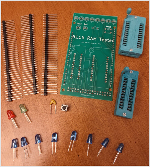
What’s Included
Assembly Instructions
You will also need an Arduino Mega, soldering supplies, wire cutters, and a PC with a USB port.
-
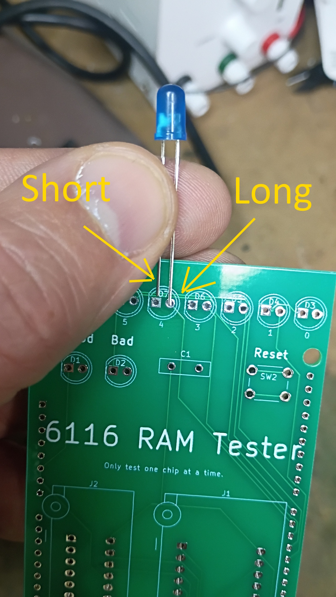
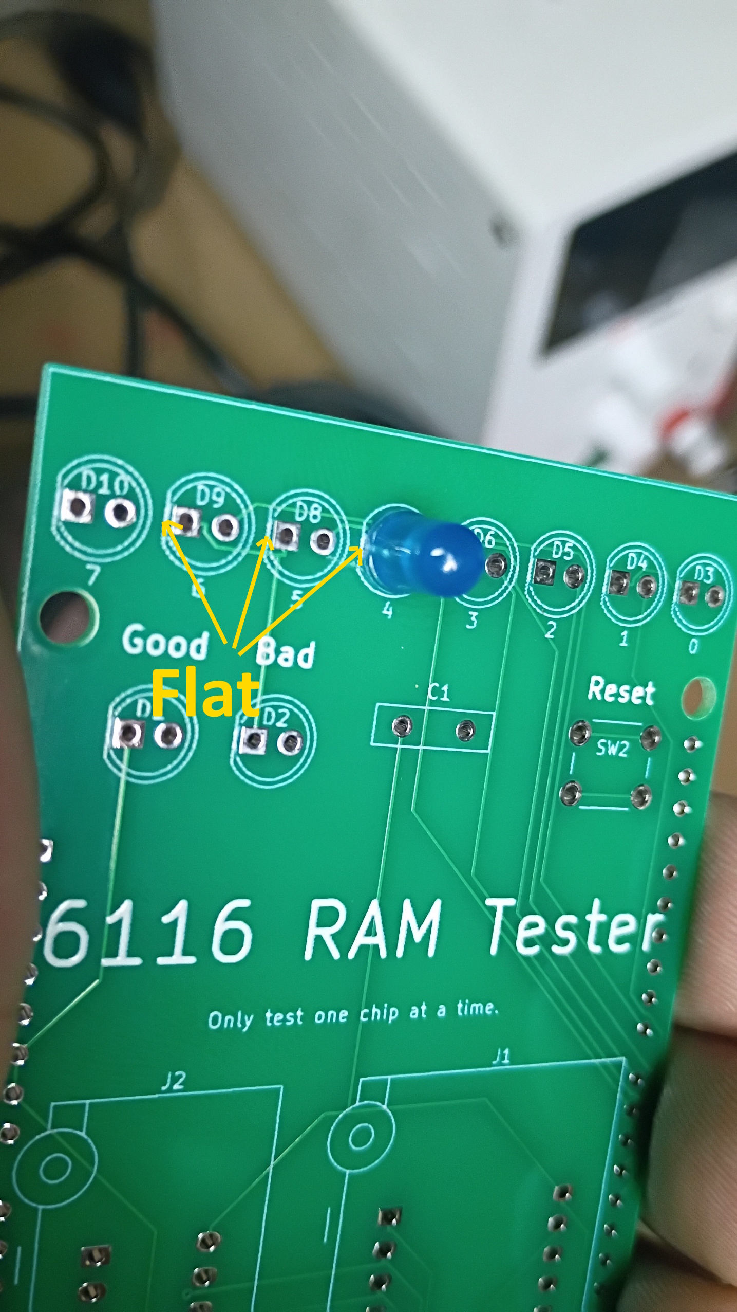
Assemble the upper components. Insert the LEDs, switches, and ZIF sockets. LEDs must be inserted in the correct orientation — the longer leg should go in the hole on the opposite side of the flat mark on the board.
-
Check your work. The board should look like this with the components inserted.
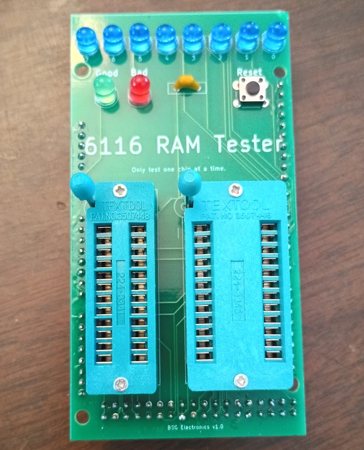
-
Flip the board over and solder in the components. Ensure that extra solder does not connect any pins. Trim the extra wire length off the LED legs.
-
Prepare the riser pins. Cut the pins to fit into the series of holes on the edges of the board. Extra pins can be saved or discarded.
-
Insert the pin sets as shown.
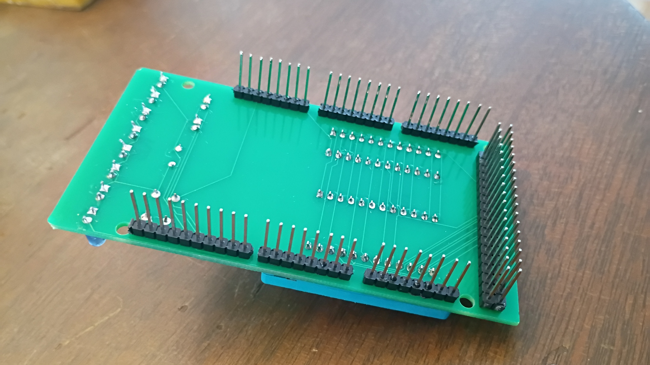
-
Solder the pins from the top of the board, then install the completed shield on your Arduino Mega.
-
Install the Arduino IDE. Download and install the Arduino IDE software.
-
Download the 6116 memory test source code. Go to the 6116-Memory-Tester repository, select Code > Download ZIP, then extract the ZIP file and save
6116-sram-tester.ino. -
Connect your Arduino Mega to your computer via USB.
-
Configure the Arduino IDE. Launch the IDE and make sure Arduino Mega and your correct COM port are both selected under the Tools menu.
-
Open the sketch. Select File > Open, then select the
6116-sram-tester.inofile you downloaded in step 8. -
Upload the sketch. Select Sketch > Upload to load the code onto your Arduino.
Note: If you encounter an upload error, retry with the shield disconnected from your Arduino.
Using the 6116 Tester
-
Insert one 6116 chip to be tested. Do not install two chips at once. The semicircle mark on the chip should point toward the LEDs (pin 1 in the upper left).
-
Plug the Arduino in with a 9V power supply or USB. The test cycle begins automatically.
-
The test takes a few minutes to complete. Solid green = good, solid red = bad.
-
Press reset to restart a test.
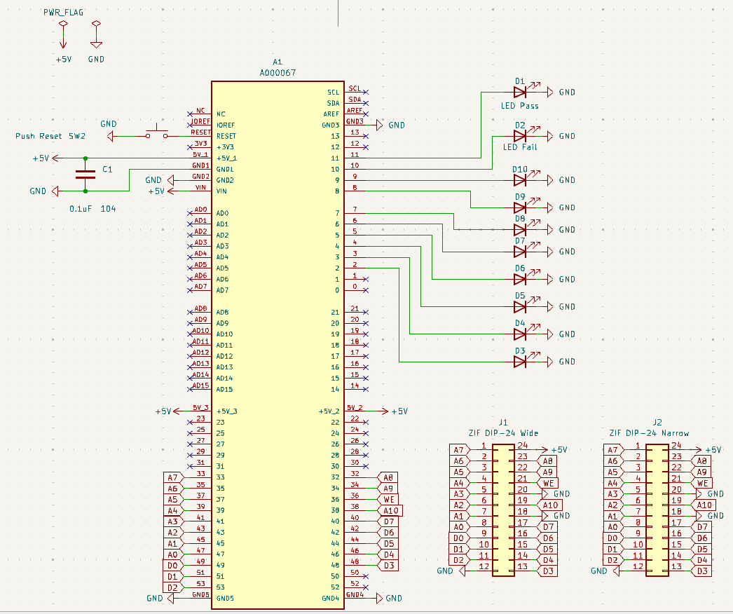
Schematic